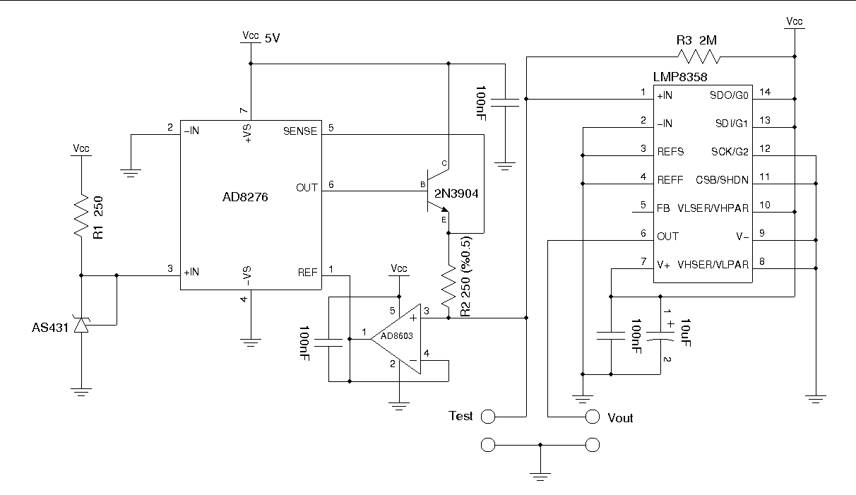
Accurate Milliohm MeasurementMost of the multimeters do not offer resistance measurement in the milliohm range. In most meters a typically Ohm range has an accuracy of 0.1 ohm and is too coarse for measuring small resistance. Of course, some of the high-end multimeters have milliohm range and there are also dedicated micro ohmmeters for even more accurate small resistance measurements, but most of them are priced way out of the range for personal use. The key in resistance measurement is nothing more than Ohm’s law. And any unknown resistance can be calculated by using either a known voltage source and measure the current or a known current source and measure the voltage drop across the resistance to be measured. Typically, small resistance in the milliohm range is measured using the 4-point Kelvin sensing method to eliminate wiring resistance of the probes and thus makes the measurement more accurate. One of the problems of measuring small resistance is that for a given current value, as the resistance to be measured goes lower, the voltage drop becomes smaller as well and in most of the cases this voltage drop becomes too small to be measured accurately. For instance the voltage generated across a 10 milli-ohm resistor from 100 mA current is only 1 mV, which is too small for most multimeters. Although the issue mentioned above can be somewhat resolved by increasing the current passed through the resistor, there is an other issue associated with this approach. Unfortunately, the heat generated from the excessive current flow affects the accuracy of the measurement. And sometimes, the target to be measured simply cannot handle current this high. To effectively measure small resistance values in the milliohm range, we need to accurately measure the current flowing through and at the same time accurately capture the minute voltage drop across the terminals. To accurately measure small voltages, one can use a programmable-gain precision instrumentation operational amplifier such as Texas Instruments‘s LMP8358. While you can use other op-amps with varies gains, one of the key benefits of using a programmable-gain gain precision instrumentation op-amp is that there is no need to match the gain setting resistors. LMP8358′s gain can be programmatically set to 10, 20, 50, 100, 200, 500 and 1000, which is superb for amplifing the millivolts voltage drop. An accurate constant current source is needed to generate a known current reference. We could use an additional multimeter to measure the current and thus eliminating the need for a current source, but it would be too cumbersome for regular use. For the ease of metering, it is usually a good idea to set the current source so that the current and voltage product is a power of 10. For instance, for a gain of 100, setting the current to 10 mA seems to be a good compromise between the current flow and the overall accuracy. The resultant measurement readings will be one 1mV per milliohm which is quite convenient. With this setting, you should be able to measure accurately down to 10 milliohm (10 mV reading). And by setting the gain to 1000 (10 mV/milliohm) we can measure resistance all the way down to 1 milliohm. The circuit for accurate milliohm measurement is shown below. It basically is a 10 mA precision current source followed by an zero-offset instrumentation amplifier with a gain of 100. 
I used the reference design for the unity-gain difference amplifier AD8276 and a precision Op-Amp AD8603 from Analog Devices to form the precision constant current source. An AS431 precision shunt voltage reference is used for the 2.5V reference voltage. Using this design, the constant load current is Vref/R2. R2 (250 Ohm) will need to have relatively high precision in order for the load current to be accurate. If you are using other precision voltage references, the value of R2 will need to be adjusted so that Vref/R2=10 mA. 
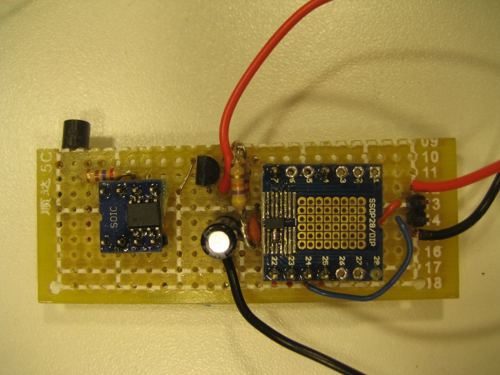
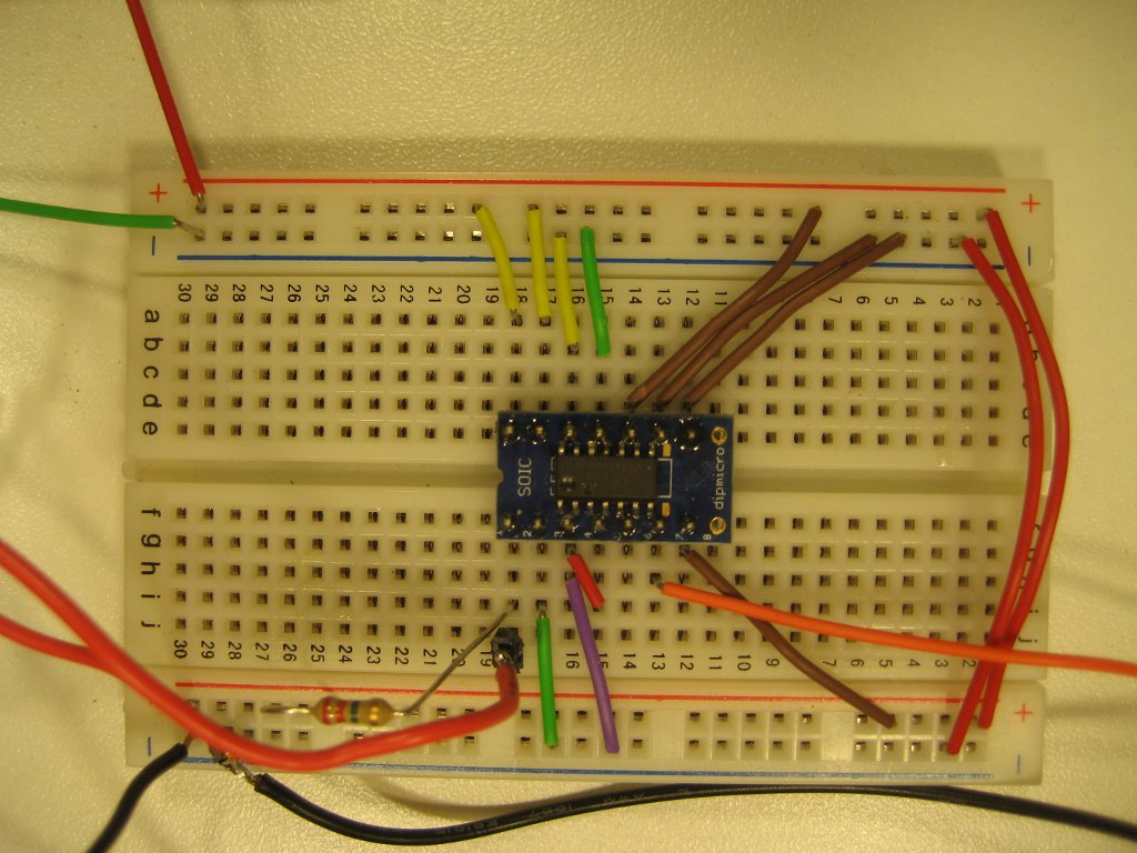
The amplifier stage uses an LMP8358 from Texas Instruments. LMP8358 can be controlled via an MCU using SPI (serial mode) or via three pins (parallel mode) for range-setting. Using an MCU to control LMP8358 has some additional advantages as some of the additional functionality such as input fault detection is only available in serial mode. But for this project, we use the pins (G2, G1, G0) to set amplifier gains directly. I may decide to switch to serial mode for the finished project as in serial mode the gains can be set more easily via commands. For now, I have setup the LMP8358 circuit on a breadboard: 
The gain for LMP8358 can be set via pin 11,12 and 13 as follows:
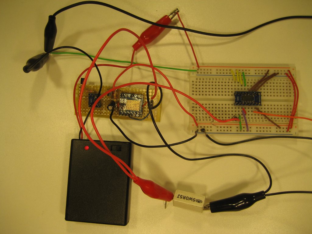
More details can be found in the datasheet. The picture below shows the measurement of a 0.5 Ohm power resistor. Note that 4-point probes were used for maximum accuracy: 
The measured voltage for the 0.5 Ohm resistor (±10%) is 0.492 V, which is dead on compared to readings obtained using a professional milliohm meter. My version of it: Bought plastic box, made holes for gain and power on switches, and on the side for banana plugs 


this is how it looks inside 
The circuit, where instead of 431 I have REF5025 from Texas Instruments, standard 0.1% grade, for 5v regulator I have LP2985A-50 also from TI, everything else is the same 
My 250R resistor was measured before installed, measured 250.0271.. I bought it 0.1%, which this one is far better
Test current is 10.01mA, I will tweak this to precise 10mA Tested 0.1R resistor 
with the circuit having 1000x gain, voltage was almost 1v, which means, that this is 97.4mR resistor. I like that :) 

miliOhm visits: |
|
Application Note on bridging audio amplifiers
A discussion on bridging audio amplifier circuits like LM3886. Includes a schematic to drive a matched pair of amplifiers in a bridged configuration, power supply considerations for LM3886 and TDA1514 power amplifier circuits-especially in bridged pairs. |
Application Note on parallel-bridging LM3886 audio amplifiers
How to make it loud - real loud. (230 watts rms into 8 ohms without clipping from 4 ICs. How to match LM3886s for parallel operation, then bridge the matched parallel banks. If you are not familiar with bridging amplifiers (BTL configuration), read the Application Note on bridging listed left in article Application Note on bridging audio amplifiers. |
| My first car audio system My second car audio system My third car audio system |
